How to set a stick welder starts with matching welding current to electrode diameter and workpiece thickness. The correct setting is a starting range rather than one universal number: welding position, electrode coating, polarity guidance, and the machine’s operating characteristics also affect the result.
Set the stick welder. make a test weld on a similar piece of material, and adjust in small increments. A weak arc or sticking electrode can indicate insufficient current, while excessive spatter or burn-through can indicate too much current.
Summary: Choose current according to electrode diameter and material thickness. Flat-position welding generally uses higher current than vertical or overhead welding. Follow the electrode manufacturer’s polarity guidance and stay within the welder’s duty cycle.
Why does a stick welder need the correct current setting?
Current directly affects arc stability and weld penetration. If current is too low, the electrode may stick, the arc may be unstable, and the weld may have limited penetration or excessive slag.
If current is too high, spatter can increase and thin workpieces may burn through. Matching the setting to the job also helps avoid operating the machine continuously beyond its intended load cycle.
What amperage should be used for common stick electrode sizes?
The ranges below are practical starting points from the supplied data. Use the lower range for vertical or overhead welding and the higher range for flat-position welding, then confirm the setting with a test weld.
| Electrode diameter | Flat position | Vertical or overhead position |
|---|---|---|
| 2.5 mm | 60–90 A | 50–80 A |
| 3.2 mm | 90–130 A | 80–120 A |
| 4.0 mm | 130–160 A | 120–150 A |
| 5.0 mm | 170–220 A | 160–200 A |
For flat-position work, the source also lists starting currents by coating type. For example, a 3.2 mm electrode is listed at 90 A with a thin coating, 100 A with a medium coating, 110 A with a thick coating, and 115 A for a high-deposition electrode.
How do workpiece thickness and electrode diameter affect the setting?
Thin workpieces require controlled heat input to reduce the risk of burn-through and distortion, while thicker workpieces need enough current and electrode capacity for adequate penetration. The source provides two starting formulas: I = S × 40 for current in amperes, and D = S / 2 + 1 for electrode diameter in millimeters, where S is workpiece thickness in millimeters.
These formulas are only initial guidance. Actual settings can vary with AC or DC output, power stability, electrode type, and the specific welder.
| Workpiece thickness | Example listed electrode/current combinations |
|---|---|
| 3 mm | 2.0 mm / 60 A; 2.5 mm / 70 A; 3.2 mm / 90 A |
| 5 mm | 2.5 mm / 90 A; 3.2 mm / 110 A; 4.0 mm / 130 A |
| 8 mm | 2.5 mm / 90 A; 3.2 mm / 125 A; 4.0 mm / 150 A |
| 10 mm | 3.2 mm / 130 A; 4.0 mm / 160 A; 5.0 mm / 190 A |
| 20 mm | 4.0 mm / 190 A; 5.0 mm / 220 A |
How should polarity and welding position be set?
For DC welding, follow the polarity recommendation printed by the electrode manufacturer. The supplied guidance describes DC+ as electrode positive and work clamp negative, while DC− is electrode negative and work clamp positive.
Welding position also changes the practical setting. Flat welding may use more current, whereas vertical and overhead welding generally call for a reduced setting to help control molten metal, porosity, and spatter.
What is the safe process for adjusting a stick welder?
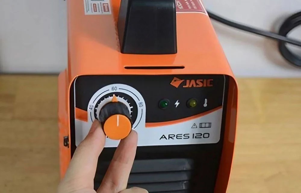
First identify the electrode type, electrode diameter, workpiece thickness, and welding position. Select an initial amperage from the relevant range, set it using the welder’s dial or digital control, and check the machine’s duty cycle before welding continuously.
Where available, verify actual output with an clamp meter. Then run a test bead on material of comparable thickness and observe arc stability, penetration, spatter, and bead shape before refining the setting.
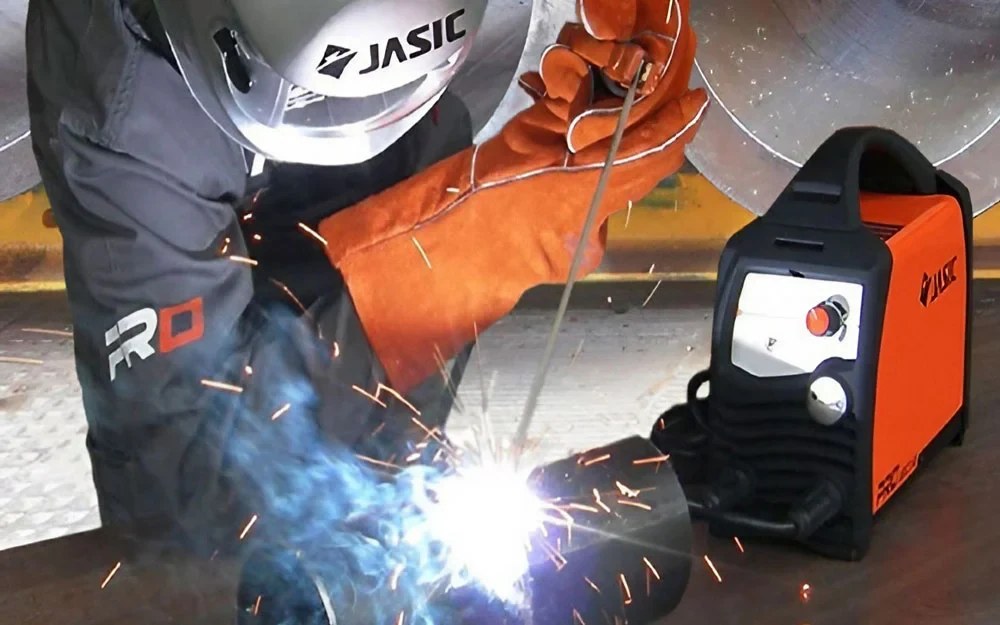
Which weld symptoms indicate that current should be adjusted?
An electrode that sticks, a weak arc, limited penetration, or heavy slag can indicate that current should be increased slightly after checking the electrode and polarity. Excessive spatter, burned edges, or burn-through indicate that current should be reduced and travel speed reviewed.
An unstable, noisy arc welding machine can also result from poor cable, work-clamp, or power connections, not only from an incorrect current setting. A high, heavily deposited bead may require faster travel or a current adjustment depending on the welding condition.
Note: A duty cycle is the percentage of a 10-minute period that a welder can operate at its rated current. For example, a 60% duty cycle at 200 A means 6 minutes of welding followed by 4 minutes of rest.