Why does a clamp meter sometimes read accurately and other times not?
In the most popular case is not come from the clamp meter itself. It’s come from principle change of current in modern electrical systems.
With equipment uses inverters or switching power supplies, current is no longer a stable sine wave. Instead, it’s broken into controlled pulses. The amplitude varies with the operating state of the device driven not only by the load, but also by internal control algorithms. That means any single reading is just a brief snapshot of a constantly changing signal. If you observe it over time, patterns start to emerge. For instance, periodic rises and drops may reflect inverter control cycles or shifting system loads.
Before questioning the meter, identify the type of load
If the system involves inverters or switching supplies, a True RMS clamp meter is essential. Rather than assuming an ideal waveform, True RMS calculates the actual effective value of the current, regardless of its shape.
How environment and handling affect clamp meter readings
A clamp meter doesn’t measure dirrect contact to the current it senses the magnetic field around a conductor. Even at the same point, a slight change in how the clamp is positioned can lead to noticeably different readings.
Measurements are influenced not only by the current in the wire, but also by the surrounding environment. In industrial panels, conductors are often packed closely together. When multiple currents flow in parallel, their magnetic fields overlap. On top of that, leakage currents, circulating currents, and electromagnetic interference can distort what the sensor picks up. In such cases, the displayed value is no longer tied to a single conductor it reflects a combination of multiple influences. Fluctuating readings are therefore a natural result of the measurement conditions, not random error.
When working near multiple conductors or high-power equipment, it’s important to account for these magnetic interactions. Consistent technique can significantly reduce variation between measurements:
Make sure the clamp jaws are fully closed
Position the conductor at the center of the jaws
Clamp only one conductor at a time
Avoid measuring too close to strong sources of interference
Prefer straight sections of wire, away from surrounding equipment
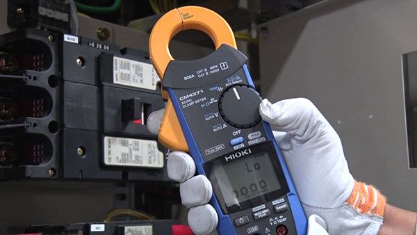
Clamp meter accuracy is not uniform across all ranges
Clamp meters are typically most accurate within their mid-range. When measuring very small currents relative to their designed range, errors tend to increase. This is why leakage current or standby current measurements can be unreliable, even when the meter is functioning properly.
Sampling rate and response time also matterespecially when capturing fast transients like motor inrush current. Events that occur in a fraction of a second can be missed if the meter isn’t fast enough.
Modern clamp meters go beyond basic readings. Many now support data logging, software integration, and real-time analysis. This allows engineers to track current trends and plan predictive maintenance more effectively.
Understanding how a clamp meter actually works doesn’t just improve accuracy it helps prevent decisions based on incomplete or misleading data.
Related articles: