
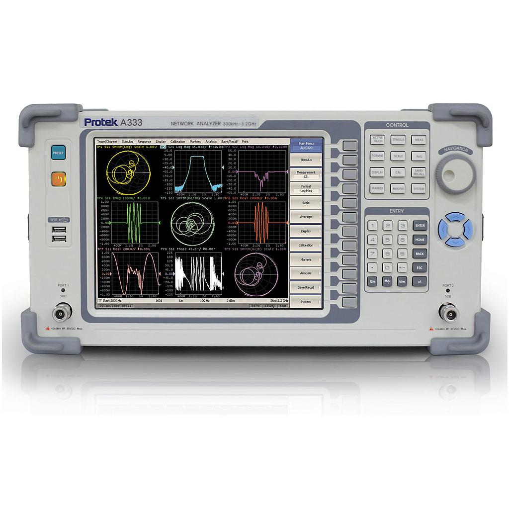
Protek A333 Network Analyzer (300Khz ~ 3.2Ghz)
ຜູ້ຜະລິດPROTEK(ເບິ່ງສິນຄ້າອື່ນໆຂອງຍີ່ຫໍ້ນີ້)
ModelA333
ຕິດຕໍ່
ການຊຳລະເງິນທີ່ປອດໄພ
ການຮັບປະກັນຄຸນນະພາບ
ປ່ຽນ ແລະ ສົ່ງຄືນງ່າຍ
ມີບໍລິການຈັດສົ່ງ
| Specifications apply under the following conditions: 40 minutes warm-up time at the ambient temperature. Environmental temperature of 20°C ± 5°C, with less than 1°C deviation from the calibration temperature. No averaging applied to data. Two port calibration is performed. | |
| Measurement accuracy | |
| Accuracy of transmission measurement (magnitude/phase) Specifications are based on a matched DUT, a measurement bandwidth of 1 Hz, and a nominal power source of –5 dBm | |
| +15 to +5 dB | 0.2 dB/2.0° |
| + 5 to -50 dB | 0.1 dB/1.0° |
| -50 to -70 dB | 0.2 dB/2.0° |
| -70 to -90 dB | 1.0 dB/6.0° |
| Accuracy of reflection measurement (magnitude/phase) Specifications are based on a matched DUT, a measurement bandwidth of 1 Hz, and a nominal source power of –5 dBm | |
| 0 to -15 dB | 0.4 dB/4.0° |
| -15 to -25 dB | 1.5 dB/7.0° |
| -25 to -35 dB | 4 dB/22.0° |
| Trace stability | |
| Temperature dependence per one degree of the temperature variation | 0.02 dB |
| Trace noise magnitude IF bandwidth 3 kHz | 0.001 dB rms |
| Measurement range | |
| Frequency range | 300kHz to 3.2GHz |
| Impedance | 50Ω ( 75Ω ) |
| Test port Connectors | N-type, female |
| Number of test ports | 2 |
| Frequency accuracy | ±5 ppm |
| Frequency resolution | 1mHz |
| Number of test points user-selectable | 2 to 10001 |
| IF bandwidth settings 1/1,5 / 2 / 3 / 5 / 7 / | 10 step 1.0 Hz to 30 kHz |
| Dynamic range IF bandwidth 10 Hz | 2 to 3200 MHz >125 dB, typ. 130dB |
| Measurement time per point 30 kHz measurement bandwidth | 125 µs |
| Test Port Output | |
| Power range | –45 to +10 dBm |
| Power accuracy | <1.0 db="" td=""> |
| Power resolution | 0.05 dB |
| Harmonic distortion | –30 dBc |
| Test Port Input | |
| Match without system error correction | >25 dB |
| Damage level | +26 dBm |
| Damage DC voltage | 35 V |
| External/Internal Reference Signal I/O | |
| Frequency | 10 MHz |
| Operating environment | |
| Temperature | +5 to +40°C |
| Dimensions (WxHxD) | 426 x 222 x 270 mm |
| Weight | 10.6 kg |
| Power supply | 100 to 240 VAC / 47 to 63 Hz |
| Measurement capabilities | |
| Number of measurement channels | Up to 16 independent measurement channels. A measurement channel is coupled to stimulus response settings including frequency range and number of points. |
| Number of windows | Each measurement channel has a display window. |
| Number of traces | Up to 16 display windows (channels) can be displayed. 16 data traces and 16 memory traces per channel |
| Measurement parameters | S11, S21, S12, S22 |
| Measurement parameter conversion | Available to convert S-parameters into reflection impedance, transmission |
| Data formats | impedance, reflection admittance, transmission admittance, and 1/S. Log magnitude, linear magnitude, phase, expanded phase, group delay, SWR, real, imaginary, Smith chart, polar. |
| Data markers | 10 independent markers per trace. Reference marker available for delta marker operation. Smith chart format includes 5 marker formats: linear magnitude/phase, log magnitude/phase, real/imaginary, R + jX, and G + jB. Polar chart format includes 3 marker formats: linear magnitude/phase, log magnitude/phase, and real/imaginary. |
| Marker functions | |
| Marker search | Max value, Min value, peak, peak left, peak right, target, target left, target right, multi-peak, multi-target, bandwidth parameters with user-defined bandwidth values. |
| Marker-to functions | Set start, stop, center to active marker stimulus value; set reference to active marker response value; set electrical delay to group delay at active marker. |
| Search range | User definable. |
| Tracking | Performs marker search continuously or on demand. |
| Time domain functions | |
| Transformation | Selectable transformation type from bandpass, lowpass impulse, lowpass step. Selectable window from maximum, normal and minimum. |
| Gated functions | Selectable gated filter type from bandpass, notch. Selectable gate shape from maximum, normal and wide. |
| Source control | |
| Sweep type | Linear sweep, segment sweep, log sweep and power sweep. |
| Segment sweep | Define independent sweep segments. Set number of points, test port power levels, IF bandwidth, delay time independently for each segment. |
| Sweep trigger | Set to continuous, hold, or single, sweep |
| Power Set | source power from -45 dBm to 10 dBm. The power slope function compensates source power level error. with internal, external, manual trigger. |
| Trace functions | |
| Display data | Display current measurement data, memory data, or current measurement and memory data simultaneously. |
| Trace math | Vector addition, subtraction, multiplication or division of measured complex values and memory data. |
| Title | Add custom title to each channel window. Titles are printed on hard copies of displayed measurements. |
| Autoscale | Automatically selects scale resolution and reference value to vertically center the trace. |
| Electrical delay | Offset measured phase or group delay by a defined amount of electrical delay, in seconds. |
| Phase Offset | Offset measured phase or group delay by a defined amount in degrees. |
| Statistics | Calculates and displays mean, standard deviation and peak-to-peak deviation of the data trace. |
| Data accuracy enhancement | |
| Measurement calibration | significantly reduces measurement uncertainty due to errors caused by system directivity, source and load match, tracking and crosstalk. Full 2-port, calibration removes all the systematic errors for the related test ports to obtain the most accurate measurements. |
| Response calibration | Simultaneous magnitude and phase correction of frequency response errors for either reflection or transmission measurements. |
| Response calibration and isolation | Compensates for frequency response and crosstalk errors of transmission measurements, and frequency response and directivity errors of reflection measurements. |
| Enhanced response calibration | Compensates for frequency response and source match errors. |
| One-port calibration | Compensates for directivity, frequency response and source match errors. |
| Full 2-port calibration | Compensates for directivity, source match, reflection tracking, load match, transmission tracking and crosstalk. Crosstalk calibration can be omitted. |
| Interpolated error correction | With any type of accuracy enhancement applied, interpolated mode recalculates the error coefficients when the test frequencies are changed. The number of points can be increased or decreased and the start/stop frequencies can be changed. |
| Reference port extension | Redefine the measurement plane from the plane where the calibration was done. |
| Other capabilities | |
| Internal hard disk drive | Store and recall instrument states, calibration data, and trace data on internal hard drive. Trace data can be saved in CSV (comma separated value) format. Instrument states include all control settings, limit lines, segment sweep tables, and memory trace data. |
| USB | Instrument states, calibration data, and trace data can be stored on an external USB drive. |
| Screen hardcopy | Printouts of instrument data are directly produced on a printer. The analyzer provides USB and parallel interfaces. |
| Familiar graphical user interface | The A333 analyzer employs a graphical user interface based on Windows. There are three ways to operate the instrument manually: you can use a hardkey interface, a touch screen interface (optional) or a mouse interface. |
| Limit lines | Define the test limit lines that appear on the display for pass/fail testing. Defined limits may be any combination of horizontal/sloping lines and discrete data points. |
| Programming function | |
| COM/DCOM Automation | |
| Remote Control | |
| LAN , GPIB ( optional ) | |
| Specifications apply under the following conditions: 40 minutes warm-up time at the ambient temperature. Environmental temperature of 20°C ± 5°C, with less than 1°C deviation from the calibration temperature. No averaging applied to data. Two port calibration is performed. |
|
| Measurement accuracy | |
| Accuracy of transmission measurement (magnitude/phase) Specifications are based on a matched DUT, a measurement bandwidth of 1 Hz, and a nominal power source of –5 dBm |
|
| +15 to +5 dB | 0.2 dB/2.0° |
| + 5 to -50 dB | 0.1 dB/1.0° |
| -50 to -70 dB | 0.2 dB/2.0° |
| -70 to -90 dB | 1.0 dB/6.0° |
| Accuracy of reflection measurement (magnitude/phase) Specifications are based on a matched DUT, a measurement bandwidth of 1 Hz, and a nominal source power of –5 dBm |
|
| 0 to -15 dB | 0.4 dB/4.0° |
| -15 to -25 dB | 1.5 dB/7.0° |
| -25 to -35 dB | 4 dB/22.0° |
| Trace stability | |
| Temperature dependence per one degree of the temperature variation | 0.02 dB |
| Trace noise magnitude IF bandwidth 3 kHz | 0.001 dB rms |
| Measurement range | |
| Frequency range | 300kHz to 3.2GHz |
| Impedance | 50Ω ( 75Ω ) |
| Test port Connectors | N-type, female |
| Number of test ports | 2 |
| Frequency accuracy | ±5 ppm |
| Frequency resolution | 1mHz |
| Number of test points user-selectable | 2 to 10001 |
| IF bandwidth settings 1/1,5 / 2 / 3 / 5 / 7 / | 10 step 1.0 Hz to 30 kHz |
| Dynamic range IF bandwidth 10 Hz | 2 to 3200 MHz >125 dB, typ. 130dB |
| Measurement time per point 30 kHz measurement bandwidth | 125 µs |
| Test Port Output | |
| Power range | –45 to +10 dBm |
| Power accuracy | <1.0 db="" td=""> |
| Power resolution | 0.05 dB |
| Harmonic distortion | –30 dBc |
| Test Port Input | |
| Match without system error correction | >25 dB |
| Damage level | +26 dBm |
| Damage DC voltage | 35 V |
| External/Internal Reference Signal I/O | |
| Frequency | 10 MHz |
| Operating environment | |
| Temperature | +5 to +40°C |
| Dimensions (WxHxD) | 426 x 222 x 270 mm |
| Weight | 10.6 kg |
| Power supply | 100 to 240 VAC / 47 to 63 Hz |
| Measurement capabilities | |
| Number of measurement channels | Up to 16 independent measurement channels. A measurement channel is coupled to stimulus response settings including frequency range and number of points. |
| Number of windows | Each measurement channel has a display window. |
| Number of traces | Up to 16 display windows (channels) can be displayed. 16 data traces and 16 memory traces per channel |
| Measurement parameters | S11, S21, S12, S22 |
| Measurement parameter conversion | Available to convert S-parameters into reflection impedance, transmission |
| Data formats | impedance, reflection admittance, transmission admittance, and 1/S. Log magnitude, linear magnitude, phase, expanded phase, group delay, SWR, real, imaginary, Smith chart, polar. |
| Data markers | 10 independent markers per trace. Reference marker available for delta marker operation. Smith chart format includes 5 marker formats: linear magnitude/phase, log magnitude/phase, real/imaginary, R + jX, and G + jB. Polar chart format includes 3 marker formats: linear magnitude/phase, log magnitude/phase, and real/imaginary. |
| Marker functions | |
| Marker search | Max value, Min value, peak, peak left, peak right, target, target left, target right, multi-peak, multi-target, bandwidth parameters with user-defined bandwidth values. |
| Marker-to functions | Set start, stop, center to active marker stimulus value; set reference to active marker response value; set electrical delay to group delay at active marker. |
| Search range | User definable. |
| Tracking | Performs marker search continuously or on demand. |
| Time domain functions | |
| Transformation | Selectable transformation type from bandpass, lowpass impulse, lowpass step. Selectable window from maximum, normal and minimum. |
| Gated functions | Selectable gated filter type from bandpass, notch. Selectable gate shape from maximum, normal and wide. |
| Source control | |
| Sweep type | Linear sweep, segment sweep, log sweep and power sweep. |
| Segment sweep | Define independent sweep segments. Set number of points, test port power levels, IF bandwidth, delay time independently for each segment. |
| Sweep trigger | Set to continuous, hold, or single, sweep |
| Power Set | source power from -45 dBm to 10 dBm. The power slope function compensates source power level error. with internal, external, manual trigger. |
| Trace functions | |
| Display data | Display current measurement data, memory data, or current measurement and memory data simultaneously. |
| Trace math | Vector addition, subtraction, multiplication or division of measured complex values and memory data. |
| Title | Add custom title to each channel window. Titles are printed on hard copies of displayed measurements. |
| Autoscale | Automatically selects scale resolution and reference value to vertically center the trace. |
| Electrical delay | Offset measured phase or group delay by a defined amount of electrical delay, in seconds. |
| Phase Offset | Offset measured phase or group delay by a defined amount in degrees. |
| Statistics | Calculates and displays mean, standard deviation and peak-to-peak deviation of the data trace. |
| Data accuracy enhancement | |
| Measurement calibration | significantly reduces measurement uncertainty due to errors caused by system directivity, source and load match, tracking and crosstalk. Full 2-port, calibration removes all the systematic errors for the related test ports to obtain the most accurate measurements. |
| Response calibration | Simultaneous magnitude and phase correction of frequency response errors for either reflection or transmission measurements. |
| Response calibration and isolation | Compensates for frequency response and crosstalk errors of transmission measurements, and frequency response and directivity errors of reflection measurements. |
| Enhanced response calibration | Compensates for frequency response and source match errors. |
| One-port calibration | Compensates for directivity, frequency response and source match errors. |
| Full 2-port calibration | Compensates for directivity, source match, reflection tracking, load match, transmission tracking and crosstalk. Crosstalk calibration can be omitted. |
| Interpolated error correction | With any type of accuracy enhancement applied, interpolated mode recalculates the error coefficients when the test frequencies are changed. The number of points can be increased or decreased and the start/stop frequencies can be changed. |
| Reference port extension | Redefine the measurement plane from the plane where the calibration was done. |
| Other capabilities | |
| Internal hard disk drive | Store and recall instrument states, calibration data, and trace data on internal hard drive. Trace data can be saved in CSV (comma separated value) format. Instrument states include all control settings, limit lines, segment sweep tables, and memory trace data. |
| USB | Instrument states, calibration data, and trace data can be stored on an external USB drive. |
| Screen hardcopy | Printouts of instrument data are directly produced on a printer. The analyzer provides USB and parallel interfaces. |
| Familiar graphical user interface | The A333 analyzer employs a graphical user interface based on Windows. There are three ways to operate the instrument manually: you can use a hardkey interface, a touch screen interface (optional) or a mouse interface. |
| Limit lines | Define the test limit lines that appear on the display for pass/fail testing. Defined limits may be any combination of horizontal/sloping lines and discrete data points. |
| Programming function | |
| COM/DCOM Automation | |
| Remote Control | |
| LAN , GPIB ( optional ) | |
ຕິດຕາມຂ່າວສານ ແລະ ຂໍ້ສະເໜີ
ຮັບສ່ວນຫຼຸດພິເສດຕາມປະລິມານ, ອັບເດດລາຄາຂາຍສົ່ງ ແລະ ການແຈ້ງເຕືອນສິນຄ້າໃໝ່ສົ່ງກົງເຖິງອິນບັອກຂອງທ່ານ.
ໂດຍການສະໝັກສະມາຊິກ, ທ່ານຍອມຮັບ ເງື່ອນໄຂການໃຫ້ບໍລິການ ແລະ ນະໂຍບາຍຄວາມເປັນສ່ວນຕົວ ຂອງພວກເຮົາ.
ການຊ່ວຍເຫຼືໍາດ່ວນ
ເຂົ້າເຖິງຜູ້ຊ່ຽວຊານທີ່ໄດ້ຮັບການຢັ້ງຢືນຂອງພວກເຮົາໂດຍກົງ