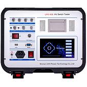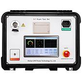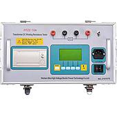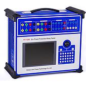
Using a lightning ground resistance tester is an important part of monitoring the condition of electrical systems and technical infrastructure. A grounding system provides a conductive path for current to flow from the grounding electrode into the earth. When the resistance value changes abnormally, the system's ability to dissipate current may be affected. Regular measurements and proper record-keeping therefore provide useful data for evaluating system performance and planning maintenance at the appropriate time.
What Is Lightning Ground Resistance ?
Ground resistance is the total impedance of the current path between the grounding electrode system and the earth. This value is directly related to the operating condition of a lightning protection grounding system. In practical applications, the objective is to ensure that current can be conducted and safely dissipated into the ground in accordance with the requirements of the installation, equipment, and applicable regulations.
A single fixed resistance threshold should not be applied to every application. Ground resistance requirements depend on the specific application as well as the relevant national or industry standards. Reference materials often mention values below 4 ohms, or lower in certain applications. However, the acceptable value should always be evaluated against the technical requirements of the specific grounding system.
Factors That Affect Ground Resistance
Ground resistance measurements reflect not only the condition of the grounding electrodes but also the surrounding soil and the installation structure. Understanding these factors helps technicians interpret measurement data more accurately rather than relying on a single measurement.
Soil Conditions and Resistivity
Soil moisture, salt content, temperature, and electrical conductivity can all affect ground resistance. Seasonal changes, dry periods, or increased soil moisture may cause measurement results to vary. When comparing data from different inspections, the soil and environmental conditions at the time of measurement should therefore be recorded to identify trends more accurately.
Grounding Electrode Structure and Installation
The material, shape, dimensions, number of electrodes, installation depth, and spacing between electrodes all affect the overall ground resistance. Any changes to the grounding system should be documented in the inspection records to support future assessment.
Corrosion and Aging
Grounding electrodes and connection points may corrode over time. This can reduce electrical contact quality and increase ground resistance. Maintaining historical measurement data makes it easier to identify abnormal increases and determine when physical inspection or corrective maintenance may be required.
How Does a Ground Resistance Tester Support Testing ?
A resistance metter is used to determine the resistance of a grounding system using an appropriate measurement method. These instruments commonly use the 3-point or 4-point measurement method. The tester applies a known current, measures the corresponding voltage between the test points, and calculates the resistance value.
The measurement method should be selected according to the site conditions, grounding system configuration, and applicable technical procedures. Operators should follow the instrument manufacturer's instructions, arrange the test leads correctly, and check the surrounding area before testing. Measurement results are most useful when the same procedure and test configuration are maintained across inspections.
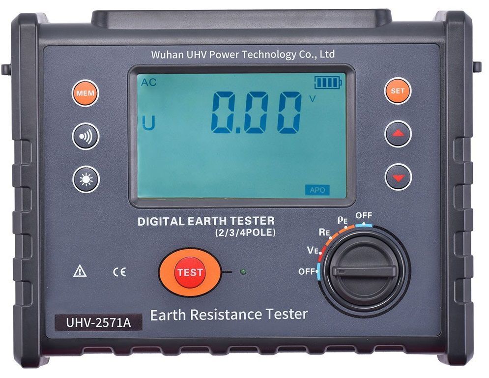
Lightning Ground Resistance Testing Procedure
Plan the inspection: Identify the grounding points to be tested, determine the inspection schedule, and select the appropriate measurement method.
Inspect the system condition: Visually check the grounding electrodes, connections, and any visible signs of damage or corrosion.
Perform the measurement: Use a ground resistance tester according to the appropriate measurement principle and test lead configuration.
Record the data: Document the measured resistance, test date, location, soil conditions, and other relevant field observations.
Analyze the trend: Compare the results with previous measurements and the technical requirements applicable to the grounding system.
What to Do When Ground Resistance Increases
When the measured resistance exceeds the specified requirement or increases significantly compared with previous measurements, the underlying cause should be investigated before selecting a corrective action. Possible measures include inspecting or replacing degraded components, adding grounding electrodes, modifying the electrode installation depth or configuration, or improving soil conditions. Any modification should comply with the system design and relevant technical requirements.
When evaluating results obtained from a ground resistance tester, it is useful to consider the measurement history together with soil conditions, grounding electrode configuration, and the condition of connections and electrodes. Combining periodic measurements, trend analysis, and maintenance when necessary provides a practical approach to maintaining the performance of the grounding system