- in high-voltage circuit breaker contacts,
- in disconnecting switches, separators, and short-circuiters,
- in packaged switchgears,
- in contact couplings,
- in weld seams, etc.
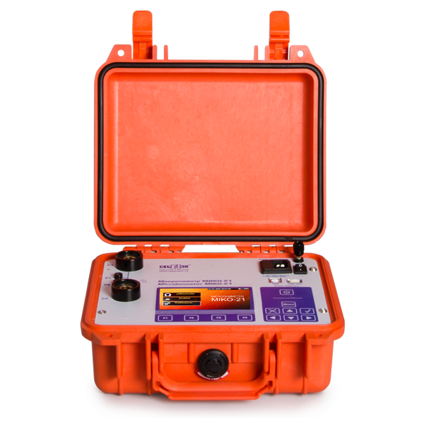
SKB EP MIKO-21 SKB MIKO-21 MicroOhm Tester (200A)
Manufacturer: SKB EP Model: MIKO-21 - Contact
Model : MIKO-21
Manuafacturer : SKB
Details
Measurement of transient resistances of electric circuits in the range of 0.1 µΩ ÷ 2 Ω, the lowest error being ±0.05%
Measurements using the rated current up to 200A
One of the problems faced when measuring the transient resistances with permissible error is availability of oxide films between contact surfaces.
According to International standard IEC 60694 "General Specifications for High-Voltage Switch Gears" (International Electrotechnical Commission), for controlling this type of error, amperage of the test current during testing the electric resistance in the main circuit of a HV circuit breaker shall be between 50A and its rated value.
Current amperage in the passport data of many foreign circuit breakers is most often limited by specific values: 100A and 200A.
Amperage in the MIKO-21 can be set in several ways:
- By selecting from a number of specified values: 10A, 50A, 100A, and 200A;
- By setting the automatic mode for selecting the test amperage;
- Manual mode for setting the test current in the range from 1 to 200 A at a step of 1A.
Special algorithms for measuring the transient resistances of high-voltage circuit breakers with in-built current transformers
Only SKB EP microohmmeters measure transient resistances (R transient) of minimum-oil and bulk-oil circuit breakers using separate automatic modes optimized for those circuit breakers. Current transformers (CT) of bulk-oil circuit breakers form a prolonged transition process when the test current is applied. For this reason the time of measurement is determined by CT parameters, by their number, amperage and, for example, for U-220-2000-25U1 circuit breaker it may be as high as 30 seconds. Special algorithms with automatic stop of measurements allow avoidance of subjective mistakes and increase the number of measurements per one battery charge.
Four methods of resistance measurement start-up
There are four methods programmed in the instrument for resistance measurement start-up:
- "Single-shot start-up", i.e., start-up by pressing START button located on the front panel of the instrument. For implementing this method the test cable clamps are first firmly fastened on the tested object and only then the user starts up measurements.
- "Start-up against circuit closing". In this case the measurement is started up after occurrence of electric contact between tested circuit and current or potential contacts of the test cable. Information obtained is displayed. This mode is used together with needle-type press contact of the test cable and is intended for rapid testing of a large number of bolt joints.
- "Regular star-up". Measurements are started up in the pre-specified time intervals. This mode can be used for items rejecting. The mode is used in the following cases: when both hands are used for pressing the cable probe against the test points and there is nobody else to press the START button; for monitoring the changing resistance, e.g., during tuning; for rejecting the kit of resistors against limiting values of resistance specified in the instrument.
- "Regular circuit". This mode is intended for regular automatic measurement start-up against the test circuit closing. The mode is initiated by pressing the START button; the measurement is started against the test circuit closing, and the instrument gives a beep. After getting the result the software automatically converts to the mode of waiting for the next circuit closing.
Archive of passport values of tested equipment
Company archive of passport values of resistances (R transient) of circuit breaker contacts ensures automatic comparison between measured and passport values subject to circuit breaker grade indication;
Archive of the instrument contains passports of HV circuit breakers with indication of maximum and/or minimum permissible transient resistances of contacts, and passports for rejected resistors with indication of permissible values of the upper and lower thresholds of resistances.
The user can also add the required template.
Automatic comparison of measured and passport values of resistances
Availability of an in-built archive of passport values of eclectic resistances (main circuit of HV circuit breakers) facilitates automatic detection, and the device beeps if the results of measurements go beyond the permissible limits.
Interactive control
Color graphic display of high brightness ensures easy reading on a sunny day, whereas intuitively understandable interface with a sensor display facilitates the instrument use.
The Instrument can be manipulated either from the film keyboard or from the sensor display, as suits.
Communication with PC via USB or a flash card facilitates data transfer from the Instrument to the Company data base.
The instrument can be built-in into testing systems under control of software complexes of diagnosis laboratories and equipment manufacturers.
Independent power supply, light weight and size
- Availability of an energy-independent memory and a mode of "automatic storage of the results of measurements" considerably reduce the full time of the circuit breaker test owing to transfer of the data obtained from the substation area to the Company office.
- The above peculiarities ensure complete independence and high mobility of the instrument over the vast substation or workshop territory as you avoid troubles with a power cable, extension rod to the socket, and grounding.
Test cable of unique and ergonomic design
For convenience the standard kit includes only one type of a test package (Kit 3 includes two test cables with crocodile clips for high-voltage circuit breakers up to 110 kV).
Suitable cable or a set of cables can be selected from a large range of additional accessories:
- Test cable, should the instrument be placed near a circuit breaker:
One set with spring-loaded contacts for measurements in busbars or in arc extinguish chambers. Two other kits with crocodile clips (with current and potential wires) for circuit breakers of up to 10 kV, circuit breakers of up to 110 kV, and a part for circuit breakers of up to 220kV.
- Test cable, should the instrument be placed in the lifter cradle:
Three kits that include cables with crocodile clips (with current and potential wires), a cable with a G-clamp (with current and potential wires). They differ in length and purpose, namely: for HV circuit breakers of up to 220kV, for HV circuit breakers of up to 330kV, some for 500kV, and for HV circuit breakers of up to 750kV.
- Test cables for precision measurements and measurements on the circuit sections with the test current is applied to their end points.
-
Specifications
Value
Range of resistance measurements, Ohm
0.1 µΩ ÷ 2 Ω
Range of test current amperage, A
1 ÷ 200
Error of measurements, %
±0.05
Time of measurement in Mode 1, sec
not more than 2.0
Time of measurement in Mode 2 on a bulk-oil circuit breaker, sec
10 ÷ 30
Time of measurement in Mode 3 on a bulk-oil circuit breaker with battery charge saving
5 ÷ 15
Period of continuous operation (in normal conditions), hrs, no less than
8
Number of tests (in normal conditions), no less than
500
Display of the instrument
Sensor, color, graphic, 480x272 dots
Types of data transfer channels
USB/USB Flash
Consumed power does not exceed, V
60
Operating temperature range, ºС
-20 ÷ +50
Weight of the test block, kg, not more than
3.1
Dimensions, mm
270х250х130
Interface language
English
User manuals language
English
Calibration period, year
3
Standard complete set
| Photo | Item, Index | Application |
|---|---|---|
 |
Test block of MIKO-21 SKB139.00.00.000 | Instrument and covering documents: calibration certificate, Operations Manual, and a log book. |
 |
Set #3 SKB039.28.00.000 | Includes: Test cable with crocodile clips (50 mm jaw capacity) for all the circuit breakers of up to 35kV, and for some circuit breakers of up to 110kV. Current and potential wires (4.5 m, 1.5 kg, 2 pcs.). |
 |
Main cable SKB018.09.00.000 | For instrument connection to the main network and for the battery charging via an in-built charger (2 m long). |
 |
Earth wire SKB010.01.00.000 | For earthing the instrument casing. Terminated with a G-clamp and a lug for a screw. Rated current is 50A (Length: 1.75m). |
 |
Shunt 75 ShSM M3 75A-0.5 | Shunt for checking the MIKO-21 operability. |
 |
Safety devices VP2B-1V-21 (ВП2Б-1В-2А) (2 pcs.). | For the power source protection. |
 |
Tool bag SKB126.06.00.000 | Robust, convenient, wear proof bag for transportation of cables, documentation and other accessories to the MIKO-21 instrument. |
Test cables, should the instrument be placed near the circuit breaker (on order)
| Photo | Item, Index | Application |
|---|---|---|
 |
Set #1 SKB039.19.00.000-01 | Includes: Test cable with spring-loaded needle-type contacts for measurements in busbars or in arc extinguish chambers. Current and potential wires (1.5 m, 0.5 kg, 2 pcs. per set). |
 |
Set #2 SKB039.27.00.000-01 | Includes: Test cable with crocodile clips (up to 50 mm jaw capacity) for circuit breakers of up to 10kV. Current and potential wires (2 m, 0.5 kg, 2 pcs. per set). |
 |
Set #4 SKB039.26.00.000-01 | Includes: Test cable with crocodile clips (up to 50 mm jaw capacity) for all the circuit breakers of up to 110kV and some circuit breakers of up to 220kV. Current and potential wires (6 m, 2 kg, 2 pcs. per set). |
Test cables, should the instrument be placed in the lift cradle (on order)
| Photo | Item, Index | Application |
|---|---|---|
 |
Set #5 SKB039.20.00.000/СКБ039.21.00.000 | A test kit consists of two cables for circuit breakers of up to 220kV:
|
 |
Set #6 SKB039.20.00.000/СКБ039.21.00.000 | A test kit consists of two cables for circuit breakers of up to 330kV, and some for up to 500kV:
|
 |
Set #7 SKB039.20.00.000/SKB039.21.00.000 | A test kit consists of two cables for circuit breakers of up to 750kV:
|
Additional accessories to the set (on order)
| Photo | Item, Index | Application |
|---|---|---|
 |
Potential spring-loaded contact (2 pcs.) SKB 023.21.00.000 | Together with test cables for avoiding high transient resistances between an input pin and a cramp of the device. To be used together with Sets ##3-7. |
 |
Potential pin contact (2 pcs.) SKB 023.22.00.000 | Together with test cables for avoiding high transient resistances between an input pin and a cramp of the device. To be used together with Sets ##3-7. |
 |
Test cable SKB039.24.00.000 | Potential cable with jackplugs. It consists of two twisted wires. It includes: crocodile clips A25C (2 pcs.), and a probe (2 pcs.). For precision measurements and for measurements on the sections of the circuit to the end points of which the test current is applied (2 m, 0.06 kg). To be used together with Set #2. |
Additional accessories (on order)
| Photo | Item, Index | Application |
|---|---|---|
 |
USB 2.0 A-B Cable | For computer connection and data transfer. |
- Quality Engagement
- Easy change and return
- Delivery Avaliable
- Favorable payment